
Sơ đồ bài lab
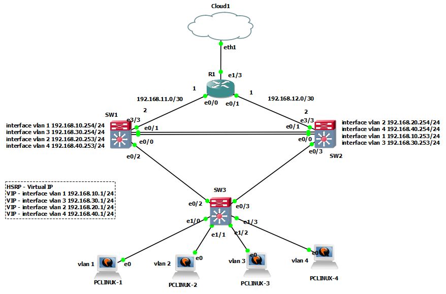
Cấu hình các thông số cơ bản cho sơ đồ
Cấu hình static trunking các đường link giữa switch và switch
//SW1
SW1#conf t
SW1(config-if-range)#shutdown
SW1(config)#int range e0/0-3 , e1/0-3 , e2/0-3 , e3/0-3
enable
conf t
interface range ethernet 0/0 – 2
shutdown
switchport trunk encapsulation dot1q
switchport mode trunk
no shutdown
exit
//SW2
enable
conf t
interface range ethernet 0/0 – 1 , ethernet 0/3
shutdown
switchport trunk encapsulation dot1q
switchport mode trunk
no shutdown
exit
//SW3
enable
conf t
interface range ethernet 0/2 – 3
shutdown
switchport trunk encapsulation dot1q
switchport mode trunk
no shutdown
exit
Kiểm tra trunking tại Switch 1 , Switch 2 , Switch 3
SW1#show interfaces trunk
Port Mode Encapsulation Status Native vlan
Et0/0 on 802.1q trunking 1
Et0/1 on 802.1q trunking 1
Et0/2 on 802.1q trunking 1
SW2#show interfaces trunk
Port Mode Encapsulation Status Native vlan
Et0/0 on 802.1q trunking 1
Et0/1 on 802.1q trunking 1
Et0/3 on 802.1q trunking 1
SW3#show interfaces trunk
Port Mode Encapsulation Status Native vlan
Et0/2 on 802.1q trunking 1
Et0/3 on 802.1q trunking 1
Cấu hình Ethernet Channel tại Switch 1 và Switch 2
//Switch 1
interface range ethernet 0/0 – 1
channel-protocol lacp
channel-group 1 mode active
exit
//Switch 2
interface range ethernet 0/0 – 1
channel-protocol lacp
channel-group 1 mode active
exit
Kiểm tra cấu hình Port-channel 1 tại Switch 1 và Switch 2
SW1#show interfaces trunk
Port Mode Encapsulation Status Native vlan
Et0/2 on 802.1q trunking 1
Po1 on 802.1q trunking 1
SW2#show interfaces trunk
Port Mode Encapsulation Status Native vlan
Et0/3 on 802.1q trunking 1
Po1 on 802.1q trunking 1
Cấu hình VTP cho các switch
//SW1
vtp mode server
vtp domain vmware.lab
vtp password 123456
vlan 2
name V2
vlan 3
name V3
vlan 4
name V4
//SW2
vtp mode client
vtp domain vmware.lab
vtp password 123456
//SW3
vtp mode client
vtp domain vmware.lab
vtp password 123456
Cấu hình Port access trên switch access
//SW3
interface ethernet 1/0
shutdown
switchport mode access
switchport access vlan 1
spanning-tree portfast
no shutdown
exit
interface ethernet 1/1
shutdown
switchport mode access
switchport access vlan 2
spanning-tree portfast
no shutdown
exit
interface ethernet 1/2
shutdown
switchport mode access
switchport access vlan 3
spanning-tree portfast
no shutdown
exit
interface ethernet 1/3
shutdown
switchport mode access
switchport access vlan 4
spanning-tree portfast
no shutdown
exit
Cấu hình Spanning Tree (STP)
– Thiết lập SW1 là Root Switch cho Vlan 1 và Vlan 3. SW1 là Root Switch dự phòng cho Vlan 2 và Vlan 4
//SW1
spanning-tree vlan 1 root primary
spanning-tree vlan 3 root primary
spanning-tree vlan 2 root secondary
spanning-tree vlan 4 root secondary
– Thiết lập SW2 là Root Switch cho Vlan 2 và Vlan 4. SW2 là Root Switch dự phòng cho Vlan 1 và Vlan 3
//SW2
spanning-tree vlan 2 root primary
spanning-tree vlan 4 root primary
spanning-tree vlan 1 root secondary
spanning-tree vlan 3 root secondary
Cấu hình Inter-Vlan và định tuyến Vlan cho Layer 3 Switch
Cấu hình Inter-Vlan cho Switch 1
//SW1
enable
conf t
interface vlan 1
ip address 192.168.10.254 255.255.255.0
no sh
exit
interface vlan 3
ip address 192.168.30.254 255.255.255.0
no sh
exit
interface vlan 2
ip address 192.168.20.253 255.255.255.0
no sh
exit
interface vlan 4
ip address 192.168.40.253 255.255.255.0
no sh
exit
Cấu hình Inter-Vlan cho Switch 2
//SW2
conf t
interface vlan 2
ip address 192.168.20.254 255.255.255.0
no sh
exit
interface vlan 4
ip address 192.168.40.254 255.255.255.0
no sh
exit
interface vlan 1
ip address 192.168.10.253 255.255.255.0
no sh
exit
interface vlan 3
ip address 192.168.30.253 255.255.255.0
no sh
exit
Cấu hình định tuyến VLAN tại SW L3
//SW1
enable
conf t
ip routing
//SW2
enable
conf t
ip routing
Lý thuyết và cấu hình cơ bản HSRP là gì ?
Lý thuyết
– Đây là giao thức FHRP của Cisco và chỉ chạy trên các thiết bị của Cisco (Hot Standby Router Protocol)
– Khi ta có 2 router đảm nhận nhiệm vụ gateway cho một dải mạng hay 1 vlan, sẽ cùng tham gia một nhóm HSRP để tạo ra một router ảo làm gateway cho dải mạng hay vlan đó.
– Với HSRP
+ Actice: router chính đảm nhận nhiệm vụ chuyển dữ liệu đi ra khỏi mạng cho các end-user
+ Standby: Router dự phòng
+ Listen: Router dự phòng cho 2 router active và standby
– Tiêu chí bầu chọn Actice cho một nhóm HSRP:
+ Đầu tiên là giá trị Priority được thiết lập trên các cổng ethernet đấu nối xuống LAN của các router tham gia group HSRP. Router nào có giá trị Priority cao nhất sẽ được bầu chọn làm Actice
+ Thứ 2 là IP. Trường hợp nhiều router có giá trị Priority bằng nhau, Router với IP cao nhất sẽ là Actice.
– Mặc định việc bầu chọn Actice/Standby của HSRP là non – preempt, tuy nhiên ta có thể thay đổi được tính chất này. Cơ chế non – preempt là cơ chế mà khi Actice/Standby router đã được bầu chọn, các router mới tham gia vào nhóm sẽ không được chiếm quyền của các router này cho dù có Priority hay IP cao hơn
Thao tác cấu hình HSRP cơ bản
– Vào interface vlan cần cấu hình HSRP
(config)# interface [name_interface]
– Cấu hình HSRP version 2
(config-if)# standby version 2
– Cấu hình số hiệu group và IP cho router ảo
(config-if)# standby [group-id] ip [IP_router_ảo]
group-id: số hiệu của nhóm HSRP mà 2 router tham gia
IP_router_ảo: địa chỉ IP gán cho router ảo.
– Cấu hình giá trị Priority để chọn router đóng vai trò Actice cho nhóm HSRP:
(config-if)# standby [group-id] priority [Giá_trị_Priority]
Giá_trị_Priority từ 0 đến 255. Mặc định là 100
– Để đảm bảo việc chuyển đổi dự phòng được diễn ra thông suốt và Router Actice sẽ luôn nắm giữ vai trò Actice khi không xảy ra sự cố, cấu hình chuyển đổi chế độ bầu chọn Actice thành pre – preempt
(config-if)# standby [group-id] preempt
– Kiểm tra trạng thái hoạt động của HSRP
# show standby brief
Cấu hình HSRP cho 2 SW L3 trong sơ đồ bài lab
Cấu hình
– Cấu hình Virtual IP cho interface vlan 1 tại SW1 và SW2. Ta cấu hình cho SW1 là Actice, SW2 là Standby
//SW1
int vlan 1
standby version 2
standby 1 ip 192.168.10.1
standby 1 authentication thanhdd
standby 1 priority 200
standby 1 preempt
//SW2
int vlan 1
standby version 2
standby 1 ip 192.168.10.1
standby 1 authentication thanhdd
standby 1 priority 100
standby 1 preempt
– Cấu hình Virtual IP cho interface vlan 2 tại SW1 và SW2. Ta cấu hình cho SW2 là Actice, SW1 là Standby
//SW1
int vlan 2
standby version 2
standby 2 ip 192.168.20.1
standby 2 authentication thanhdd
standby 2 priority 100
standby 2 preempt
//SW2
int vlan 2
standby version 2
standby 2 ip 192.168.20.1
standby 2 authentication thanhdd
standby 2 priority 200
standby 2 preempt
– Cấu hình Virtual IP cho interface vlan 3 tại SW1 và SW2. Ta cấu hình cho SW1 là Actice, SW2 là Standby
//SW1
int vlan 3
standby version 2
standby 3 ip 192.168.30.1
standby 3 authentication thanhdd
standby 3 priority 200
standby 3 preempt
//SW2
int vlan 3
standby version 2
standby 3 ip 192.168.30.1
standby 3 authentication thanhdd
standby 3 priority 100
standby 3 preempt
– Cấu hình Virtual IP cho interface vlan 4 tại SW1 và SW2. Ta cấu hình cho SW2 là Actice, SW1 là Standby
//SW1
int vlan 4
standby version 2
standby 4 ip 192.168.40.1
standby 4 authentication thanhdd
standby 4 priority 100
standby 4 preempt
//SW2
int vlan 4
standby version 2
standby 4 ip 192.168.40.1
standby 4 authentication thanhdd
standby 4 priority 200
standby 4 preempt
Kiểm tra
– Kiểm tra trạng thái hoạt động của HSRP trên SW1 và SW2
SW1#show standby brief
Interface Grp Pri P State Active Standby Virtual IP
Vl1 1 200 P Active local 192.168.10.253 192.168.10.1
Vl2 2 100 P Standby 192.168.20.254 local 192.168.20.1
Vl3 3 200 P Active local 192.168.30.253 192.168.30.1
Vl4 4 100 P Standby 192.168.40.254 local 192.168.40.1
SW2#show standby brief
Interface Grp Pri P State Active Standby Virtual IP
Vl1 1 100 P Standby 192.168.10.254 local 192.168.10.1
Vl2 2 200 P Active local 192.168.20.253 192.168.20.1
Vl3 3 100 P Standby 192.168.30.254 local 192.168.30.1
Vl4 4 200 P Active local 192.168.40.253 192.168.40.1
– Tạo các pool dhcp cấp phát IP cho các máy end-user để ping test
//SW1
conf t
ip dhcp pool net1
network 192.168.10.0 /24
default-router 192.168.10.1
dns-server 8.8.8.8
exit
ip dhcp pool net3
network 192.168.30.0 /24
default-router 192.168.30.1
dns-server 8.8.8.8
exit
ip dhcp excluded-address 192.168.10.1
ip dhcp excluded-address 192.168.30.1
//SW2
conf t
ip dhcp pool net2
network 192.168.20.0 /24
default-router 192.168.20.1
dns-server 8.8.8.8
exit
ip dhcp pool net4
network 192.168.40.0 /24
default-router 192.168.40.1
dns-server 8.8.8.8
exit
ip dhcp excluded-address 192.168.20.1
ip dhcp excluded-address 192.168.40.1
– Tại các máy end-user ping test
+ Xin cấp lại dhcp
dhclient -r
+ Kiểm tra gateway
ip route
+ Kiểm tra IP
ifconfig
+ Ping đến các IP khác trong mạng
root@box:~# ping 192.168.10.2
+ Xóa các địa chỉ đã cấp phát trên SW1 và SW2
SW1#clear ip dhcp binding *
SW1#show ip dhcp binding
+ Thử tắt 1 SW để test kiểm trường hợp 1 SW L3 bị sự cố
Cấu hình để các end-user có thể ra internet
Cấu hình IP đấu nối cho các SW L3 và router
//SW1
conf t
interface ethernet 3/3
no switchport
ip address 192.1.11.2 255.255.255.252
no shutdown
exit
//SW2
conf t
interface ethernet 3/3
no switchport
ip address 192.1.12.2 255.255.255.252
no shutdown
exit
//R1
conf t
interface ethernet 0/0
ip address 192.1.11.1 255.255.255.252
no shutdown
exit
interface ethernet 0/1
ip address 192.1.12.1 255.255.255.252
no shutdown
exit
Cấu hình để ra internet
– Cấu hình default-router và nat trên R1
//R1
conf t
interface ethernet 1/3
ip address dhcp
no shutdown
ip nat outsite
exit
interface ethernet 0/0
ip nat insite
interface ethernet 0/1
ip nat insite
exit
access-list 1 permit 192.168.10.0 0.0.0.255
access-list 1 permit 192.168.20.0 0.0.0.255
access-list 1 permit 192.168.30.0 0.0.0.255
access-list 1 permit 192.168.40.0 0.0.0.255
ip nat insite source list 1 interface ethernet 1/3 overload
– Cấu hình định tuyến động cho R1, SW1, SW2
//SW1
conf t
interface e3/3
no switchport
ip address 192.168.11.2 255.255.255.252
no shutdown
exit
router eigrp 10
no auto-summary
network 192.168.11.0
network 192.168.10.0
network 192.168.20.0
network 192.168.30.0
network 192.168.40.0
//SW2
conf t
interface e3/3
no switchport
ip address 192.168.12.2 255.255.255.252
no shutdown
exit
router eigrp 10
no auto-summary
network 192.168.12.0
network 192.168.10.0
network 192.168.20.0
network 192.168.30.0
network 192.168.40.0
//R1
router eigrp 10
no auto-summary
network 192.168.11.0
network 192.168.12.0
redistribute static